

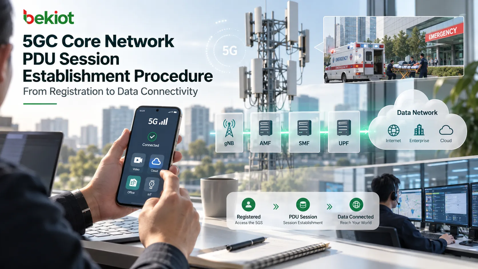
A UE can complete 5G registration while applications still cannot reach the Internet. Registration establishes access and mobility context; PDU Session Establishment creates the session that connects the UE to a data network. A 5G icon or Registration Accept alone proves neither session establishment nor successful packet forwarding.
This guide follows a new UE-requested session over 3GPP access, using the non-roaming or local-breakout procedure as its reference. Home-routed roaming, emergency sessions, access transfer and Control Plane CIoT optimizations have additional or different branches. The ordinary N3 user-plane sequence below is not a universal flow for every deployment.
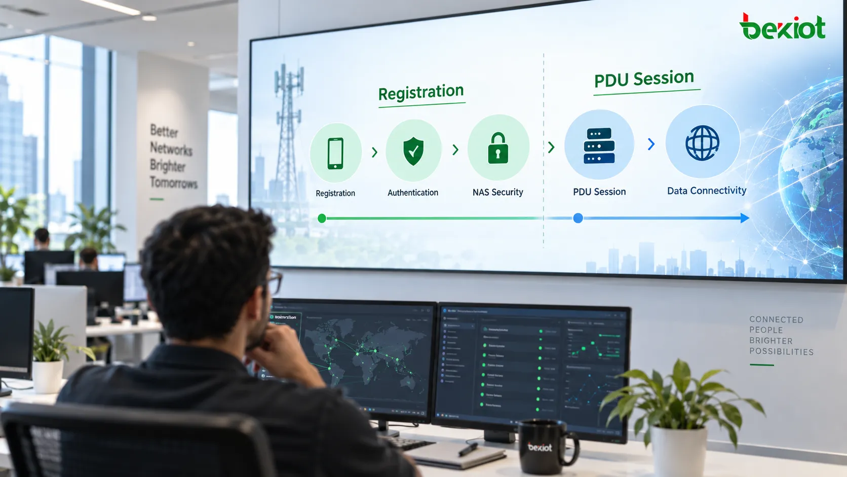
Registration and PDU Sessions have different jobs
The AMF coordinates identity handling, authentication, NAS security and registration-management context. A PDU Session adds the DNN, S-NSSAI, serving SMF, user-plane anchor and authorized session parameters needed for data service. Internet, IMS and enterprise connectivity may use different sessions.
In EPC terminology, a PDN Connection contains EPS Bearers. In 5GS, the corresponding learning model is a PDU Session containing QoS Flows; a default QoS rule does not create an LTE Default EPS Bearer. A registered UE can have no PDU Session, or several sessions for different services. Establishment can occur near registration or later when connectivity is needed.
For an IP-type PDU Session, address allocation or configuration is part of connectivity setup. Ethernet and Unstructured PDU Session Types also exist, so an IP address is not a universal outcome. This article's IP-address examples apply to IP sessions.
Read the NAS transport and the inner session request separately
The UE sends a PDU Session Establishment Request in an N1 SM container carried by UL NAS TRANSPORT. DNN, S-NSSAI, Request Type and PDU Session ID used for AMF routing must be distinguished from the inner 5GSM message. The inner request identifies the session and requests parameters such as PDU Session Type and SSC Mode; the surrounding transport supplies routing context.
PDU Session ID distinguishes sessions belonging to one UE. SUPI identifies the subscriber, not an individual session.
DNN identifies the target data network and contributes to SMF selection, UPF selection and policy decisions.
S-NSSAI identifies the network slice. The requested combination must be compatible with allowed slices, subscription and network capabilities.
Request Type distinguishes an initial request from an existing-session or emergency-related case. Do not infer a new session from the message name alone.
Requested parameters are inputs to authorization, not guaranteed results. Check which DNN and S-NSSAI are actually selected and whether the allowed PDU Session Type and SSC Mode match the intended service.
The AMF selects an SMF and creates the SM Context
The gNB forwards NAS signaling to the AMF through NGAP, with access and location information such as TAI and NR-CGI. It does not select session policy or UPF forwarding rules; it later controls the required radio resources.
The AMF selects an SMF able to serve the DNN and S-NSSAI. NRF discovery can return candidates for the Nsmf_PDUSession service using slice, DNN and serving-network information. Selection also depends on deployment policy. Cached discovery, local configuration or SCP routing can change which discovery exchanges appear in a trace.
The AMF invokes Nsmf_PDUSession_CreateSMContext, carrying subscriber and session identifiers, selected routing information and the N1 SM container. The SMF takes responsibility for session control, while the AMF continues access and mobility management and transports N1/N2 information.

Subscription data and policy bound the session
The SMF obtains the relevant Session Management Subscription Data from the UDM when required and can subscribe to changes. Data associated with the DNN and S-NSSAI can constrain PDU Session Type, SSC Mode, Session-AMBR and default QoS. An IPv4 request, for example, still needs an authorized compatible session type.
The SMF also registers its serving relationship for the subscriber and session with the UDM at the applicable stage. Retrieval, subscriptions and registration are separate operations; their order and reuse depend on the procedure and existing context. They should not be treated as one mandatory repeated transaction for every request.
Where dynamic SM Policy Control is deployed, the SMF selects a PCF and establishes an SM Policy Association. Subscriber identity, DNN, S-NSSAI, location and subscribed QoS can inform the authorized policy. Where applicable, external data-network authentication or authorization is another conditional check.
The SMF reconciles the UE request, subscription limits and applicable policy before configuring user-plane treatment. PCF involvement and individual rules depend on the service and deployment; a missing optional exchange does not by itself establish a fault.
N4 turns session requirements into UPF rules
The SMF selects a suitable UPF using factors such as DNN, slice, topology and UE location. Over N4, it uses PFCP to establish or modify the required user-plane session. In the ordinary new-session case, a PFCP Session Establishment Request installs the initial rules.
PDR identifies packets belonging to a session or traffic flow and references the applicable processing rules.
FAR specifies forwarding, dropping, buffering or other supported treatment for matching packets.
QER provides applicable QoS enforcement, including gate or rate controls.
URR defines applicable usage measurement and reporting.
These rules work together; not every session needs an identical collection. Inspect the PDR references as well as the rule contents. A correct FAR attached to the wrong PDR still produces incorrect forwarding.
The UPF response identifies its PFCP session using an F-SEID and returns allocated user-plane tunnel information where applicable. A PFCP F-SEID identifies control-plane session state; an N3 F-TEID identifies a GTP-U tunnel endpoint. They are not interchangeable. Tunnel information can be allocated according to the supported procedure rather than always being created in one fixed way.
At this point, the UPF-side N3 information can be ready while the gNB-side downlink endpoint is still unknown. A successful initial PFCP exchange therefore does not complete the whole data path.
N1 and N2 coordinate radio resources and the N3 tunnel
The SMF invokes Namf_Communication_N1N2MessageTransfer to provide two distinct payloads. N1 SM information carries PDU Session Establishment Accept toward the UE, including negotiated parameters and authorized QoS rules as applicable. N2 SM information supplies the RAN with session and QoS Flow information and the UPF-side uplink tunnel endpoint.
Keep the message layers separate when checking DNN, S-NSSAI and address information. Not every parameter associated with the overall procedure is an information element inside the inner Accept. For an IPv6 session, subsequent IPv6 address configuration can also be required.
The AMF sends an NGAP PDU Session Resource Setup Request. The gNB allocates the applicable radio and N3 resources and delivers the NAS Accept to the UE. Its PDU Session Resource Setup Response reports accepted or failed resources and the gNB-side downlink tunnel information.
The AMF forwards the N2 result through Nsmf_PDUSession_UpdateSMContext. The SMF then uses PFCP Session Modification as required to supply the gNB endpoint and update downlink forwarding. Check both IP address and TEID: the receiving endpoint allocates the TEID used for that direction.
The ordinary user path is UE → gNB → N3 GTP-U → UPF → N6 → data network, with the reverse path for downlink. Multiple UPFs and deployment-specific routing can extend this model. NAS acceptance, RAN resource setup and actual end-to-end traffic are separate evidence checkpoints.

Troubleshoot the first failed checkpoint
Confirm registration and capture the UE request at the AMF. Compare the outer routing parameters and inner 5GSM request, including session ID, Request Type, DNN, S-NSSAI, PDU Session Type and SSC Mode.
Check SMF selection and SM Context creation. Correlate subscriber and session identifiers across NAS and service-based signaling, then examine any rejection cause or service error.
Check subscription authorization, applicable PCF policy and any required external authentication. Separate a denied service from a transport failure.
Check PFCP results, PDR/FAR/QER/URR relationships and direction-specific tunnel endpoints. Confirm the gNB result and any subsequent N4 modification.
Observe uplink and downlink GTP-U on N3, then traffic on N6. Check routing, return paths, address configuration and DNS as applicable. A working tunnel does not prove the target application is reachable.
Use the first failed checkpoint to narrow the fault to NAS, service-based signaling, N4, RAN/N3 or the data network. Repeating authentication checks after a valid session Accept is rarely useful unless the trace points back to registration or security.
FAQs
Does registration automatically establish a PDU Session?
No. The procedures are separate. A UE can remain registered without a session and request one later. Session timing depends on UE behavior, configured services and network policy.
Does an Accept prove that Internet service works?
No. Verify RAN resources, both N3 directions, UPF rules and N6 reachability. For an IP session, also check address configuration and the intended data network; not every DNN provides public Internet access.
Why is N4 modification seen after establishment?
The gNB endpoint can become available only after RAN resource setup. The SMF then updates the UPF so that downlink packets use that endpoint. Read the actual changed rules rather than treating every modification as a new session.
Are QFI and QER the same?
No. QFI identifies a QoS Flow in 5GS. QER is a PFCP QoS Enforcement Rule in the UPF and can carry an applicable QFI. An identifier and an enforcement rule serve different purposes.
Related procedures and standards
For the preceding access procedure, see 5G initial registration. For removal of an existing session, see PDU Session Release; releasing one session need not deregister the UE.
The reference flow is specified in 3GPP TS 23.502, clause 4.3.2.2.1. Message contents and NAS transport are defined in 3GPP TS 24.501, while PFCP rules and tunnel parameters are defined in 3GPP TS 29.244.